Click on picture for large view
HDTV at WBAL TV Baltimore
The long process of installing the new transmitter and antennas is almost complete. The new combo VHF/UHF antenna is now sitting atop the tower. The feed lines are in place, the transmitter is nearly ready to make power into the antenna, providing viewers with digital TV.
Click on picture for large view
There were many people involved, and many steps in the process along the way. Below is a summery of the process that began back in July this year.
The beginning of HDTV at WBAL TV
Wednesday, July 14, 1999
WBAL TV Baltimore, Maryland is in the process of adding HDTV broadcasting. This new digital format will be simulcast along with the current NTSC analogue broadcast. The installation of the new transmission line has begun on the TTI broadcast tower. We switched over to our backup antenna, which is also located on the TTI tower, so that the old 6" transmission can be removed. New 7" coaxial transmission line that will carry the NTSC analog and HDTV digital is being installed this week.
|
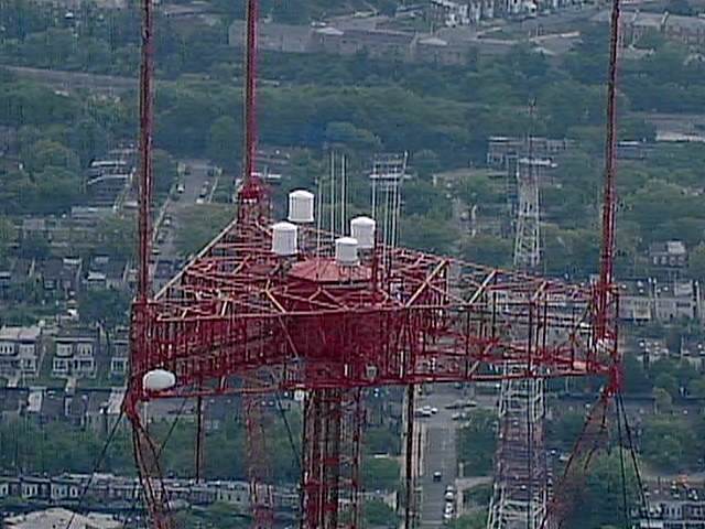
View of TTI tower top. |
View of TTI tower from the bottom |
View at the top of the tower from our helicopter. The old WBAL TV tower located on Violet Avenue can be seen in the distance.
 Click on picture for large view.
 Click on picture for large view.
 Click on picture for large view.
Monday, August 09, 1999
The installation of two of the main coaxial transmission lines is complete. We have now switched the VHF transmitter back the new main coaxial line, and the main antenna. A third "backup" coaxial line will be run as a backup for either the UHF, or the VHF coaxial feed lines.
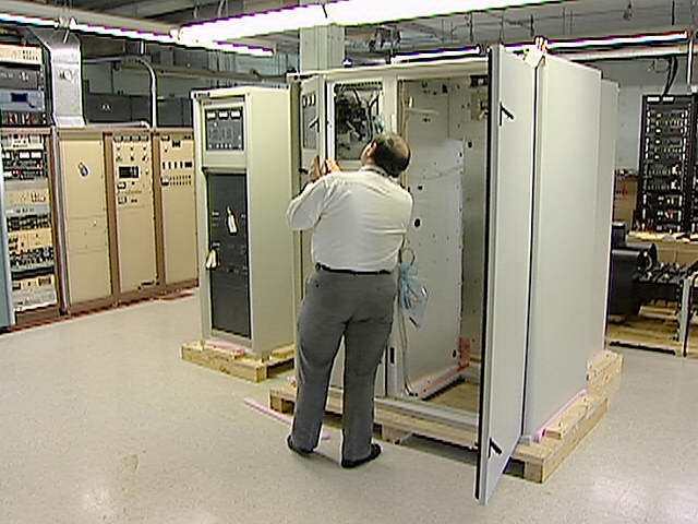
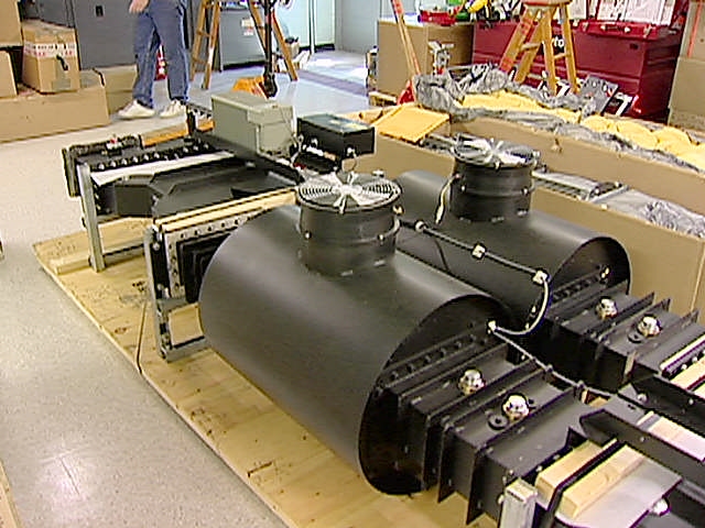
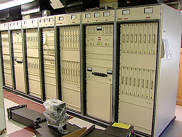
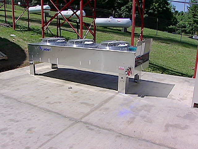
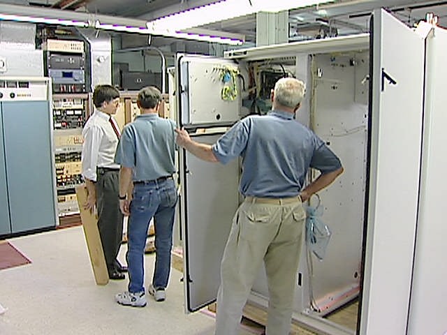
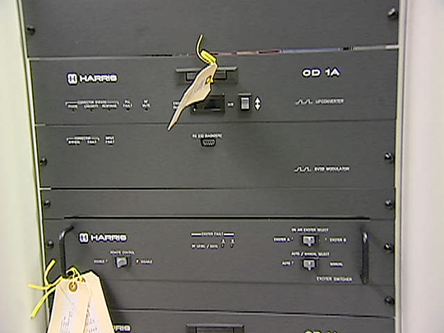
Installation of the Harris UHF DTV transmitter is well under way. The Harris Sigma uses IOT Klystrode water-cooled tubes, requiring an external heat exchanger. The heat exchanger and pump systems are in place, and will be connected into the transmitter this week. The cabinet with dual exciters, and power supplies have been installed in the transmitter room. They will share the room with the existing Larcan VHF transmitter. A "combiner" is used to match the output of both sides of the UHF transmitter, and is located in the rear of the transmitter room.
 Click on picture for full view.
 Click on picture for full view.
 Click on picture for large view.
 Click on picture for large view.
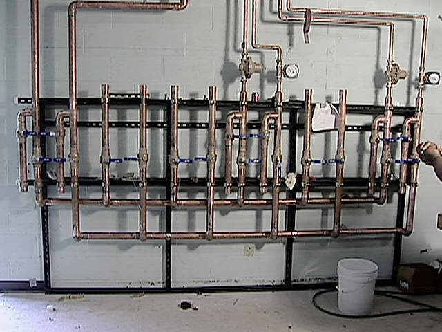
A system of ball valves is used in the manifold system to allow cooling water to be routed to any of the transmitters, as well as the reject load, and dummy load.
 Click on picture for large view.
Tuesday, August 24, 1999
 Click on picture for large view..
 Click on picture for large view.
Click on picture for large view.
The next step is to remove the existing RCA antenna, and install a Dielectric "combo" antenna that will transmit both the current NTSC analogue VHF broadcast, and the new HDTV digital UHF signals to the viewers.
 Click on picture for large view.
During the antenna change out, we would need to operate on our backup antenna. Our present backup antenna was a single bay "bat wing" style antenna. This antenna would not provide adequate coverage during this extended period. A new Dielectric three bay "bat wing" style antenna was installed. The backup antenna hangs upside down under the main antenna.
 Click on picture for large view.
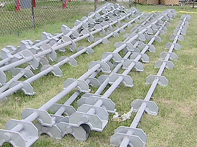
It was decided to remove the old antennas using a crane mounted on top of the tower. The tower would first have to be strengthened to allow for the additional weight of the new "combo" antennas. New diagonal steel bracing was added to the last 250 feet of the tower, as well as tower leg stiffeners.
 Click on picture for large view.
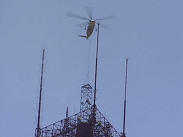
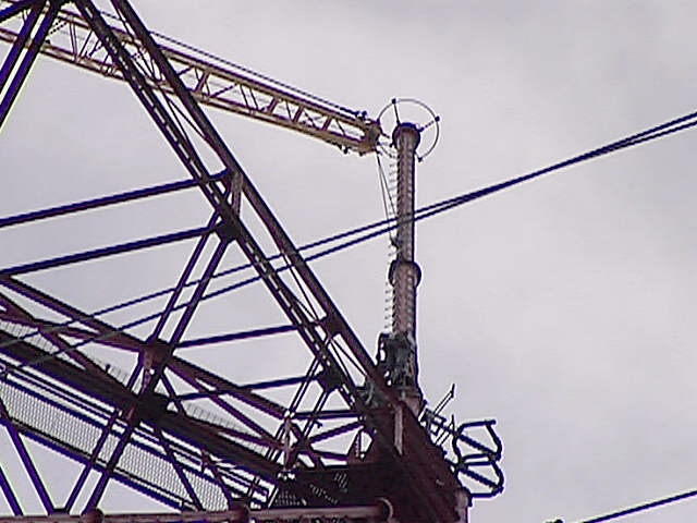
A tower extension was built to allow a crane to be positioned above the three existing antennas. The Tower extension, as well as the crane was lifted, and flown by helicopter to the top of the tower. The crane was used to lift out the old antennas, and set in place the new antennas.
|
|
|
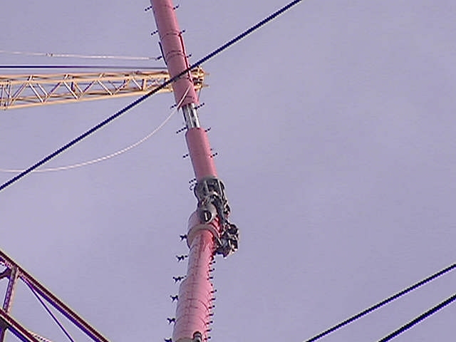
The VHF NTSC portion of the antenna is being lowered into position. The UHF HDTV antenna is then positioned on top and bolted into place.
|
|
|
John Jacob